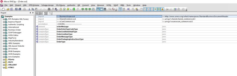
MBM Document on PO Release – Status 20
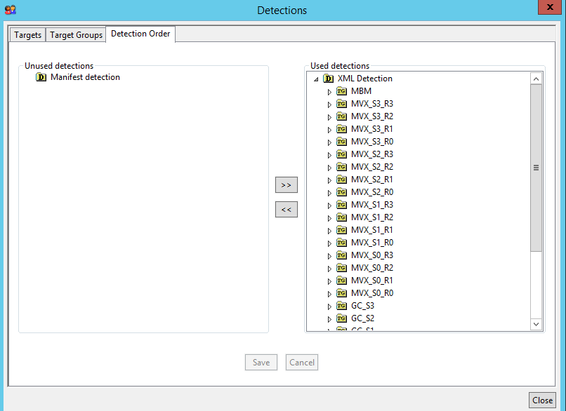
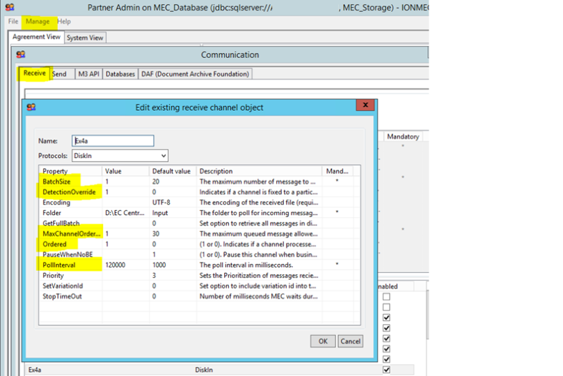
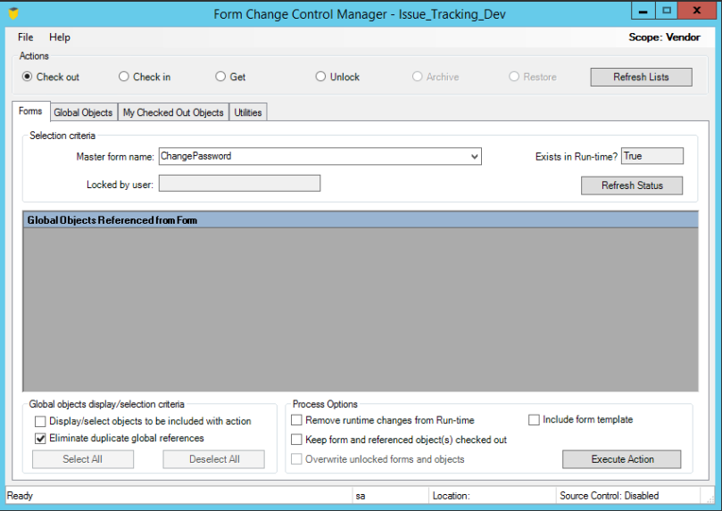
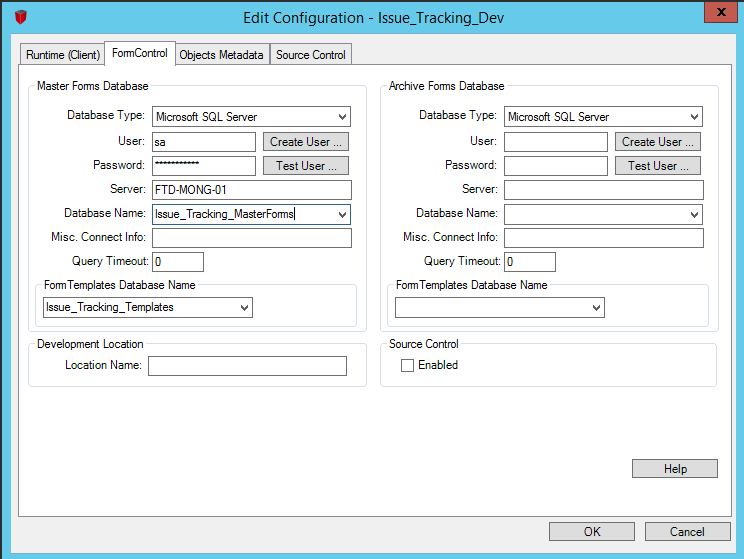
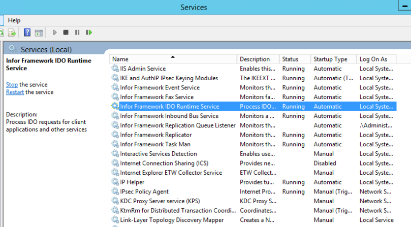
Configure the MBM listener channel
MvxNGIn:
Use this protocol for MBM initiator XML files sent from M3 (Java). Enable the default channel provided by MEC to receive MBM initiator files first. This has to be done in the Partner Admin Tool.
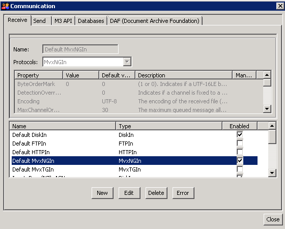
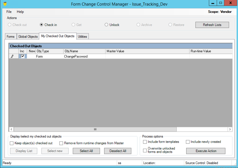
By reloading the MEC Communication Channels in LCM it will populate the default channel which is enabled above in the available channels.
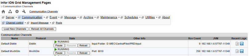
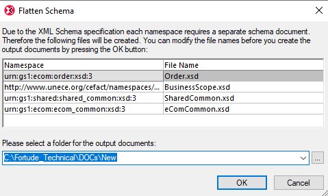
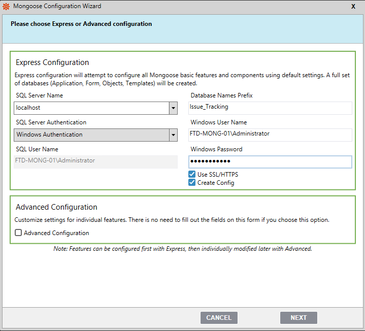
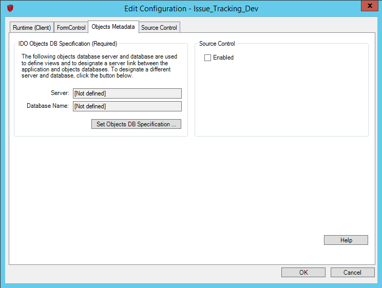
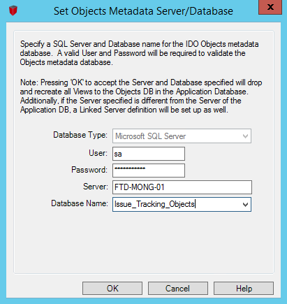
Gather Information for further configurations:
Server IP : xxx.xxx.xxx.xxx / Port: xxxx
Configure M3 Control programs
CRS116 – Media format setup
If the MBM media format is not available generate it via F14 by open Actions
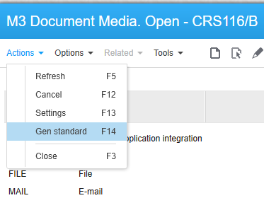
Then MBM should be available as a Media format as below
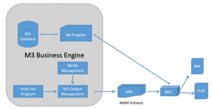
XMLOUT is also technically a stream file, although in XML format. Compared to STREAM, the XMLOUT file only contains control information and keys to the business data, instead of declaring the full set of data. This approach is chosen, since the target with XMLOUT is to utilize event-driven architecture for integration of applications.
This means that M3 only publishes documentation of what has happened. It is up to the receiving application (the output service) to interpret what to do with the event and to create the full content, since that is connected to the interpretation of the event. The way to build up content is then made through the M3 APIs.
Finally, the output service creates the media format out of the content and publishes it through the defined channel. This architecture might seem complicated at first, but it is highly efficient in the long run.
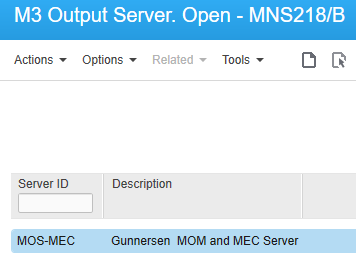
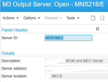
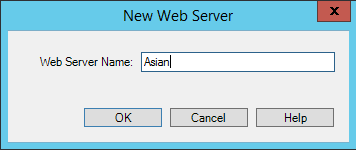
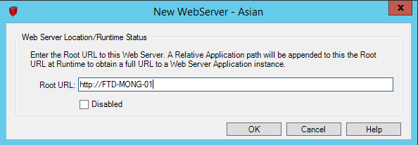
MNS218 – Define the output server
Create a new record in MNS218 for the new MEC channel. Server IP and Port can be retrieved from the LCM
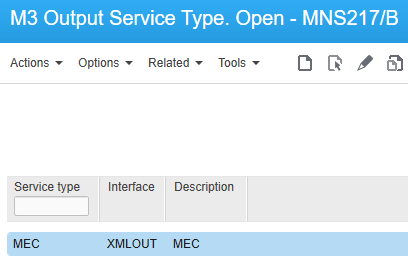
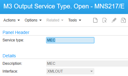
MNS217 – Define the output service
Create a new record in MNS217 for the the XML OUT service type. Set the interface property as XMLOUT
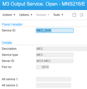
MNS216 – Map the output server and service type
Define the output service in MNS216. The service type should be the service type you defined in the MNS217. The server ID should be the server you defined in MNS218. The port number can be get from the LCM
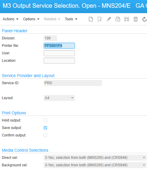
MNS204 – Connect media with output service
Define media settings for user-controlled document output. The output can be distributed as a printout, PDF file, fax or email
| Field |
Description |
| Printer file |
If this field is left blank, the setup will be valid for all printer files. |
| Hold output |
Specifies whether the output is sent to ‘Output. Manage per Job’ (MNS206) and then held there and not distributed further. This is desirable when testing new output services. |
| Save output |
Specifies whether the output is saved after it is sent to the output service. This acts as an archive function if it does not exist in the output service type software or used for tests. |
| Confirm output |
Specifies whether the output is confirmed or changed in (MNS212) before it is printed. |
| Media control selection |
Connect media control objects from ‘Output Media Selection. Open’ (MNS205) and ‘M3 Document. Connect Media’ (CRS949) to the output service settings. |
CRS928 – Define Basic Data for Document Output Management
Basic data includes media codes and how they are related to the technical format of the printer file, output server, output service and its type.
The relationships between the other basic settings are:
- The media code defines a certain format and way to distribute a document, such as via e mail. Examples of the technical format of the printer file are, *STREAM or *XMLOUT.
- An output server is the physical server that hosts an output service function.
- The output service type is a piece of software that can perform one or several output services.
- The output service definition connects the output server and output service type to a specific output service ID.
For the PPS601 Document no is: 105
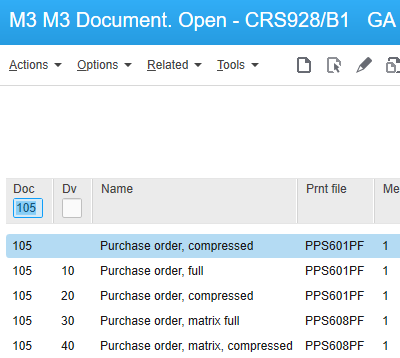
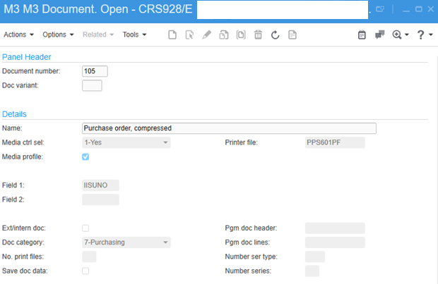
Field1 / Field 2 are the control fields for the initiator file. In this scenario it use the Supplier Number only.
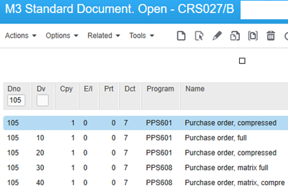
CRS027 – Generate Documents per Company
Select F14=’Generate standard’ to generate all standard documents for the company you are working in. A simple way to define the documents to use is to generate all and then remove the ones you do not want.
CRS929 – Connect Media to Documents
Define the media support per document number. By connecting a document number to a media code, it is declared that the combination is valid for the company.
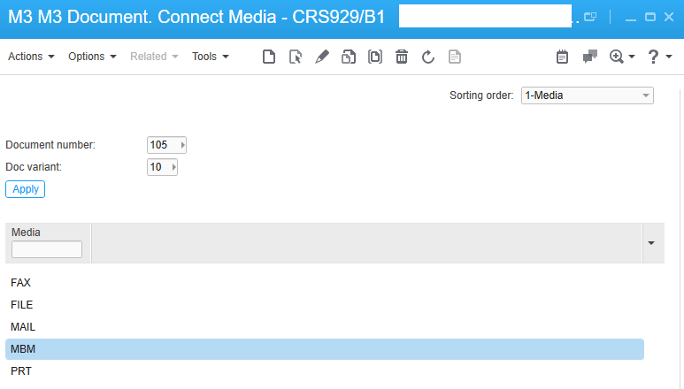
Apply the Document no, Document variant and then select the option MBM and click Next.
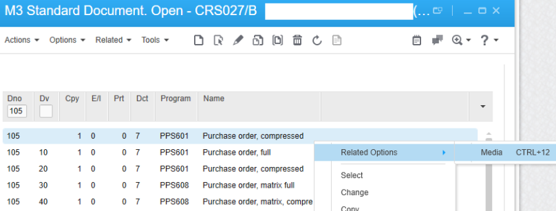
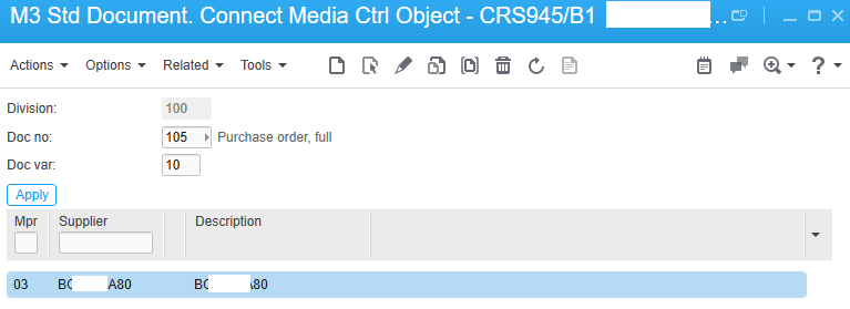
CRS945 – Connect Media Control Object for Document No 105
Select Std document and press option 12=Media to proceed to ‘Std Document. Connect Media Ctrl Object’ (CRS945/B1)
Enter a media control object and press Create to proceed to the E panel.
Enter a name and description.
Press Enter to finish and return to (CRS945/B1).
 Press option 12=Media to proceed to ‘Doc Media Control Object. Connect Media’ (CRS949/B1)
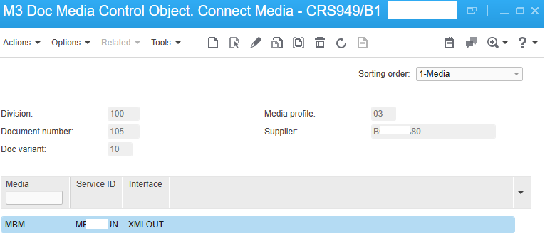
Enter the media code by pressing F4 and selecting a form of media valid for the document.
Press Create
Depending on which form of media you are defining, the E, F, G, H, or J panels will be displayed
For the EDI and MBM J panel will be displayed
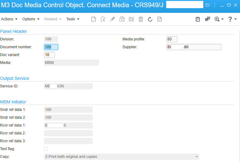
Define Media EDI and MBM (J Panel)
- Apply the Document No and Document variant as per above.
- Enter the service provider to be used for the output from M3.
- Enter the identity of the receiver.
- MBM Initiator values will be use in PAT to identify the detection.
- Enter whether you want to use a test message (also known as a test flag).
- Enter whether you want copies of previously printed documents to be printed.
- Press Enter to finish and return to (CRS949/B1).
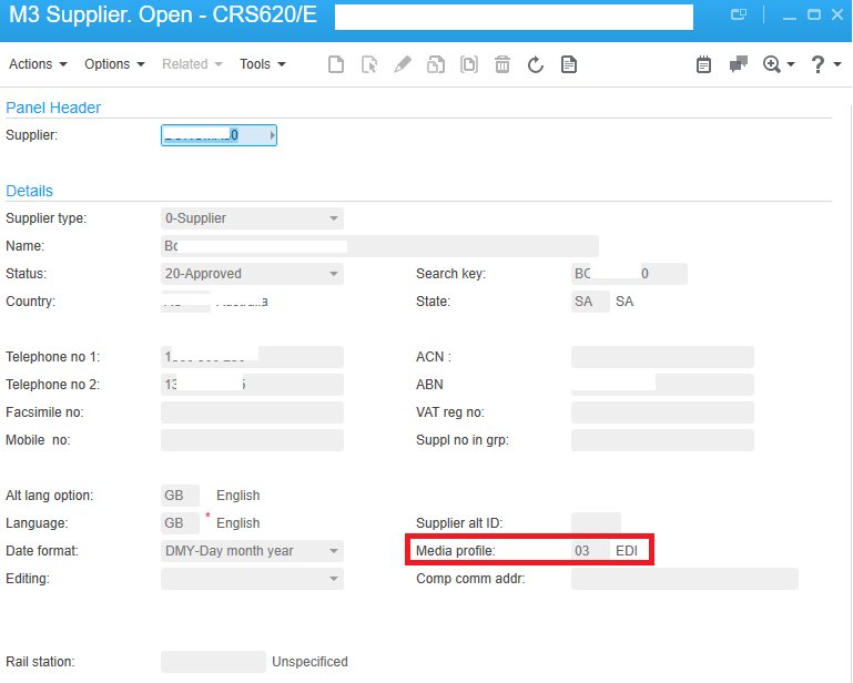
Setup the Media Profile for the Supplier – Final Step
Setup Supplier Media Controller
Open CRS620 Supplier and select a supplier.
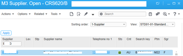
Set up the Media Profile as EDI. (This will be activate after the BE restart)
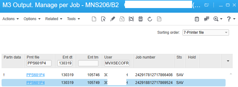
Create a new PO and Release (Print – Status 20)
In MNS206 there will be two records for the PO Printer file
Output XML
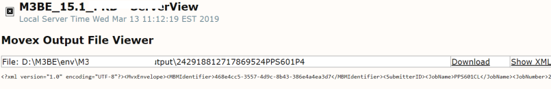
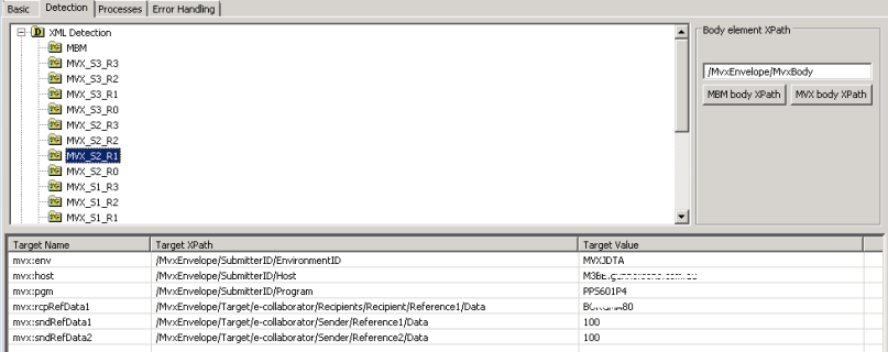
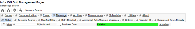
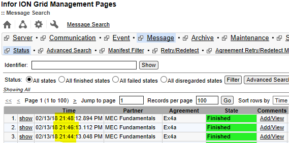
MBM Message will be detect in IEC
References:
https://docs.infor.com
-37.832294
144.922214


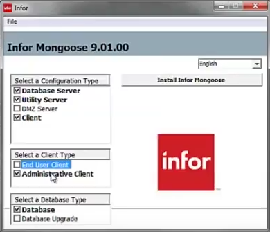


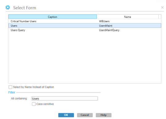
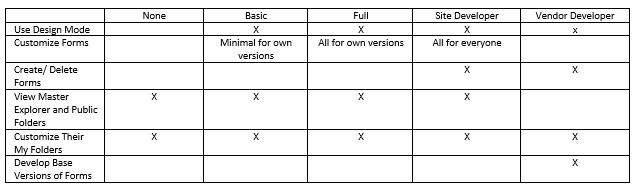
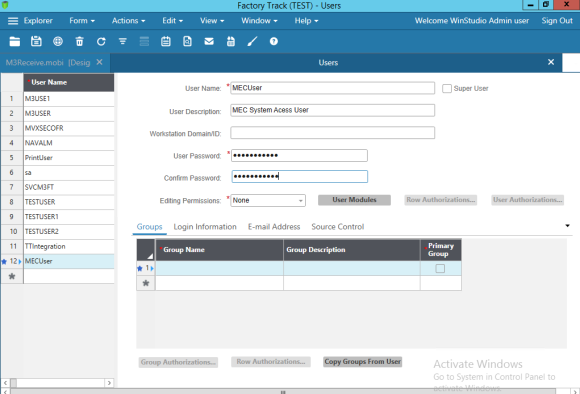 Note:- If you want to allow all the component access and development environment permission make as ‘Super User’ check box.